Table of Contents

What’s extrusion system ?

Polymer extrusion is a high-volume manufacturing process where a thermoplastic polymer is melted and forced through a die to create a continuous, uniform shape. This process forms products with a constant cross-section, such as pipes, tubes, films, and sheets, and involves melting the polymer in a heated barrel and pushing it through a die by a rotating screw.

How the process works

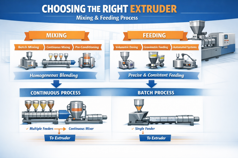
The process begins with raw plastic material, usually in pellet form, being fed into a hopper.

    • Hoppers
      • Standard stainless steel hopper (gravity feed)
      • Jacketed/dryer-mounted hopper for hygroscopic resins
      • Agitated hopper for poor-flow materials (regrind, flakes)
    • Blending & Dosing
      • Gravimetric blender (most precise; recipe control)
      • Volumetric blender (lower cost)

The pellets fall into a heated barrel where a rotating screw pushes them forward. The heat from the barrel and the mechanical shearing from the screw melt the plastic.

    • Feed Zone (Solids Conveying Section)
      • Move solid pellets forward and start preheating them.
    • Compression (Transition) Zone — Where Melting Actually Happens
      • Convert solids into a homogeneous melt.
    • Metering Zone (Melt Pumping Section)
      • Deliver uniform, bubble-free melt at constant pressure to the die.

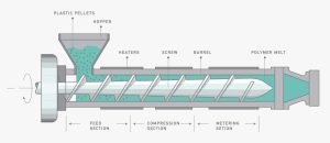
The molten polymer is then forced through a die, a shaped opening that gives the product its final cross-section.

    • Screen Changer (before die)
      • Manual screen pack
      • Hydraulic screen changer (continuous operation)
      • Continuous belt screen changer for recycled materials
    • Melt Pump (Gear Pump)
      • Stabilizes pressure & flow to the die
      • Essential for tight tolerances (sheet, film, medical tubing)
    • Die Types
      • Pipe die (spiral mandrel, basket type)
      • Profile die (custom shapes, window profiles)
      • Sheet/flat die (coat-hanger or T-die)
      • Film die (blown film annular die, cast film flat die)
      • Wire coating/crosshead die
      • Strand die (for pelletizing)

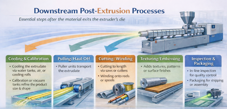
The newly formed shape is cooled, often with water or air, to solidify it and set its final form.

    • Cooling Methods
      • Immersion water bath
      • Spray cooling
      • Air cooling (for small profiles)
      • Chill rolls (for sheet & cast film)
      • Cooling rings (for blown film)
    • Temperature Control
      • Water chillers
      • Heat exchangers
      • Recirculating pumps with filtration

After cooling, the solidified product is pulled, cut to the desired length, and inspected.

    • Cutting Systems
      • Flying knife cutter (profiles, pipes)
      • Planetary cutter (large pipes)
      • Guillotine cutter (sheets)
      • Rotary cutter (tubing)
      • Pelletizer (strand, underwater, die-face)
    • Post-Processing
      • Coilers (tubing, small pipe)
      • Stacking tables
      • Printing/marking units (inkjet, embossing wheel)
      • Online inspection (laser gauge, ultrasonic thickness gauge)

Scale type of extrusion

Extrusion equipment is categorized into four primary scales: benchtop, lab, pilot, and production, which are used sequentially during product and process development to manage material use, validate processes, and achieve commercial output.

The key characteristics and uses of each scale are outlined below:

Benchtop (Micro-scale)
  • This is the smallest scale, typically used for early-stage research and development (R&D) and initial formulation testing.
    • Throughput: Very low, from 0.05 kg/h, which is ideal when using expensive active pharmaceutical ingredients (APIs) or novel materials.
    • Screw Diameter: Often 5–12 mm.
    • Application: Ideal for teaching, initial sample production, and feasibility studies.
Lab-scale
  • These systems are used for process study, optimization, and quality control in a laboratory environment.
    • Throughput: Small, allowing engineers to test parameters and predict behavior on a larger scale with minimal material waste.
    • Screw Diameter: Commonly 16–20 mm, suitable for R&D and early process validation.
    • Application: Developing and refining recipes and processes before committing to larger machines.
Pilot-scale
  • These machines bridge the gap between lab R&D and full commercial manufacturing.
    • Throughput: Higher than lab scale, allowing for small-batch production and process optimization under real-life conditions, with typical outputs up to 50-100 kg/h.
    • Screw Diameter: Generally 25–34 mm, with attributes similar to production-scale equipment, making scale-up more predictable.
    • Application: Used for clinical trials, process validation, and small commercial runs.
Production-scale
  • These are full-size industrial machines designed for continuous, high-volume manufacturing.
    • Throughput: Very high, optimized for mass production to lower costs and maximize output.
    • Screw Diameter: Typically 40-70 mm and larger.
    • Application: Commercial manufacturing where demand exceeds supply and continuous operation is key.
    • The progression through these scales allows for efficient development, ensuring that a process optimized at the pilot stage can be seamlessly transferred to a production environment using geometrically scalable equipment designs.

Single Screw vs Twin Screw Extruder

A single-screw extruder is simpler and more cost-effective for processing simple, homogeneous materials, while a twin-screw extruder uses two intermeshing screws to provide superior mixing, venting, and flexibility for more complex, higher-value materials. Twin-screw extruders offer better performance and consistency, especially with high-viscosity materials or complex formulations, while single-screw extruders are better for higher-volume, basic applications like pipes or film.

  • Single-screw extruders are often preferred for standard polymer extrusion (like pipes and sheets) and certain food applications due to their simplicity, efficiency, and consistent output for less demanding mixing tasks.
  • Twin-screw extruders (co-rotating or counter-rotating) are widely used in compounding, masterbatch, and pharmaceutical HME due to their superior mixing capabilities and ability to handle high-viscosity materials and complex formulations.

Feature 

Single-Screw Extruder

Twin-Screw Extruder

Mechanism

A single, helical screw rotates to convey, melt, and homogenize materials through friction and pressure.

Two intermeshing screws rotate together, allowing for more efficient mixing, conveying, and venting.

Materials

Best for simple, homogeneous materials like granular polymers.

Ideal for complex formulations, high-viscosity materials, and plastic modification.

Performance

Sufficient for basic applications; mixing is less intensive.

Superior mixing, kneading, and dispersing capabilities.

Applications

General extrusion of pipes, tubes, and simple films.

Plastic compounding, foam extrusion, and recycling.

Cost

Lower initial and maintenance costs.

Higher initial cost but can be justified by superior performance and versatility.

Applications for extruder

Extruders have diverse applications across multiple industries, playing a crucial role in processing materials through a continuous, controlled shaping process. Key applications span the pharmaceutical, food, polymer, compounding, and masterbatch sectors.

 Applications by Industry

Industry 

Specific Applications

Purpose

Pharmaceutical

Hot melt extrusion (HME), wet granulation, spheronization feedstock preparation, implant/device manufacturing

Enhances drug solubility and bioavailability, controlled drug release, shaping medical devices.

Food & Feed

Cereal production, snack foods, pasta, pet food, modified starches, textured vegetable protein (TVP)

Cooking, shaping, texturizing, expanding, and creating consistent product forms.

Polymers & Plastics

Pipe/sheet/film extrusion, wire coating, fiber production (filaments), profile extrusion

Continuous shaping of plastic products, insulation for wiring, production of synthetic fibers .

Compounding

Alloying/blending different polymers, incorporating additives (fillers, colorants, stabilizers)

Creating customized plastic materials with specific physical properties tailored for specific uses .

Masterbatch

Dispersing high concentrations of pigments or additives into a carrier resin

Producing concentrated color or additive pellets that are later diluted during final product manufacturing.

Downstream applications for an extruder

Extrusion is a high-volume manufacturing process used across various industries, and its downstream applications encompass a wide range of continuous products and intermediate materials. The specific application depends heavily on the material being extruded (plastics, metals, rubber, food, pharmaceuticals) and the final desired form.

  • Pipes and Tubing: Production of rigid or flexible plastic pipes for plumbing, gas lines, and drainage, as well as medical tubing and conduits.
  • Profiles: Creation of complex, irregular cross-sections for items such as window and door frames, deck railings, weatherstripping, gaskets, and decorative moldings.
  • Films and Sheets: Manufacturing of thin films (blown or cast) for various types of packaging, agricultural uses, and construction, as well as rigid sheets for advertising displays, architectural decoration, and thermoforming products (e.g., food containers).
  • Filaments and Fibers: Production of filaments for 3D printers and synthetic fibers for textiles (e.g., nylon, polyester, acrylic).
  • Wire and Cable Insulation: Applying an insulating or protective jacketing layer to electrical wires and cables.
  • Compounding/Pelletizing: The extruded material (often a blend of polymers, additives, and fillers) is cut into pellets, which are then used as raw material for further processing in other methods like injection molding or blow molding.
  • Food Products: In the food industry, applications include the production of various items such as expanded snacks, breakfast cereals, pasta, meat analogues (textured vegetable protein), pet foods, and specific confectionery items like licorice.
  • Pharmaceutical and Medical Products: Applications in this sector involve hot-melt extrusion (HME) for creating dissolvable oral thin films, enhancing drug bioavailability, and producing specialized medical tubing and other devices.

How to choose the right extruder

Mixing and feeder to extruder

Mixing and feeding to an extruder involves combining raw materials for consistent quality and then precisely delivering them into the extruder. This process can be done in batches or continuously, with automated gravimetric feeders ensuring accuracy. Pre-mixing and conditioning the materials before they enter the extruder is crucial to prevent inconsistent quality, pressure fluctuations, and product defects.

Purpose: To create a homogeneous mixture of ingredients, as the extruder has limited ability to mix materials. Poor homogeneity can lead to inconsistent final product quality.

    • Methods:
      • Batch mixing: Ingredients are mixed together, then the entire batch is fed to the extruder.
      • Continuous mixing: Multiple feeders supply individual ingredients to a continuous mixer, which then continuously feeds the extruder.
      • Conditioning: Mixers may also be heated to pre-condition powders before they are fed to the extruder. 

Purpose:  To provide a continuous and precise flow of the material mixture into the extruder’s inlet.

Importance: Even small fluctuations in the feed rate can cause pressure and output fluctuations, leading to defects like irregular dimensions or bubbles on the product’s surface.

    • Methods:
      • Volumetric dosing units: These ensure a continuous and consistent flow.
      • Gravimetric feeders: These measure the weight of the material to ensure a high-precision and accurate feed rate.
      • Automated systems: Modern systems use automated handling and vacuum conveyors to ensure consistency, reduce labor costs, and prevent contamination.
    • Continuous vs Batch: 
      • Continuous: Multiple feeders may be used to precisely dose each ingredient into a continuous mixer, which then feeds the extruder.
      • Batch: A single feeder supplies a pre-mixed batch to the extruder. 
  • Material form:  Mixing and feeding can be complicated if materials are in different forms (e.g., fine powder, pellets, regrind).
  • Consistency:  A consistent raw material mix or pre-blended masterbatch is critical for consistent machine operation and product quality.
  • Automation:  Automated, gravimetric systems offer precise control over the mix and a continuous supply to prevent problems like underfilling.
  • Cleaning:  Systems with “Easy Clean” options are available for easier cleaning during production changes. 

Downstream Post-Extrusion Processes

After the material exits the extruder’s die, a series of essential downstream operations take place to form, finish, and prepare the final product:

  • Cooling and Calibration: The hot extrudate is cooled (using air, water tanks, or cooling rolls) and sized (using calibrators or vacuum tanks) to ensure it maintains the correct shape and dimensional accuracy.
  • Pulling/Haul-off: Puller units transport the material along the production line at a consistent speed to prevent deformation.
  • Cutting/Winding: The continuous product is cut into specific lengths using saws or cutters, or wound onto reels/spools (for films, wires, or tubing).
  • Texturing/Embossing: Surface finishing processes may be applied to achieve specific textures or patterns.
  • Inspection and Packaging: In-line measurement systems inspect the product for quality control before it is prepared for shipping or assembly.

Cleaning and maintenance of an extruder system

Cleaning an extruder involves purging the machine with a cleaning material and then manually cleaning the screw and barrel. Maintenance includes daily checks of temperatures and noises, weekly checks of oil levels and filters, and monthly/quarterly inspections of wear and tear on components like gears, screws, and motors. Regular maintenance prevents clogs, improves productivity, and extends the life of the machine.

1. Prepare the machine

Power on the machine and heat the barrel to the appropriate temperature for the material being purged. Stop the material feed.

2. Purge the system

Insert a purging compound, such as a cleaning resin, into the hopper and run the extruder until the material exits cleanly.

3. Remove the screw

Lower the barrel temperature to a safe level to allow for handling, but ensure it’s not too low to make the plastic hard and difficult to remove. Remove the die head and, using a tool as a lever, push the screw out of the barrel.

4. Clean the screw

Use a wire brush and scraper to remove excess plastic from the screw flights. For stubborn residue, wrap a piece of copper gauze around a flight and move it back and forth.

5. Clean the barrel

Once the screw is out, clean the barrel using the same methods, such as a wire brush attached to a drill with copper gauze, and then wipe it clean with a lint-free cloth.

6. Reassemble and test

Reinstall the screw, reattach the die head, and perform a test run to ensure all parts are clean and functioning correctly. 

Maintenance checklist

  • Check motor and gearbox temperatures and listen for unusual noises.
  • Monitor all barrel temperature zones for consistency.
  • Check pressure readings and for any oil leaks.
  • Ensure cooling fans are operational. 
  • Check the gearbox oil level and quality.
  • Grease bearings according to manufacturer specifications.
  • Clean cooling water strainers and filters. 
  • Record motor bearing temperatures and oil pressure readings.
  • Inspect the screw for wear patterns.
  • Verify that all safety guards are secure. 
  • Check for shaft or drive misalignment.
  • Inspect screw cooling rotary unions for leaks.
  • Clean the ventilation system for inverters. 

Rheometer to Extruder: Process Mapping

In polymer compounding practice, the torque rheometer, the internal mixer, and the twin-screw extruder should be understood as three tightly connected stages of a single technical pathway that takes a formulation from laboratory concept to stable, large-scale production. All three machines perform “mixing,” but they do so with different intents, different scales of material, and fundamentally different mixing philosophies. When viewed together, they provide a complete understanding of how a formulation behaves rheologically, how it responds to intense mechanical forces during dispersion, and how it can be translated into a controlled, continuous manufacturing process.

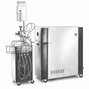
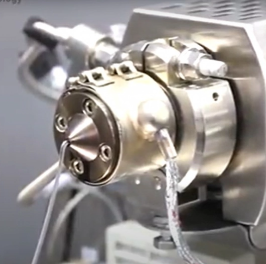
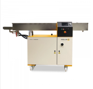
Figure 1 Torque Rheometer

A torque rheometer is used at the earliest stage, where the objective is to understand the material rather than to produce it. Only a small quantity of material, often between 30 and 80 grams, is placed into a temperature-controlled mixing chamber equipped with counter-rotating rotors. As the rotors turn at a set speed, the instrument continuously measures torque, temperature, and time with high precision. What emerges is the well-known torque–time processing curve, which is essentially a rheological fingerprint of the formulation under shear. The first rise in torque during charging reflects how the dry blend behaves as a bulk solid. This part of the curve provides information about particle friction, bulk density, and the influence of lubricants or fillers on feeding behavior. As mixing proceeds and the polymer begins to soften, a dramatic torque peak appears when individual particles fuse into a coherent mass. This fusion peak is extremely important because it reveals how quickly the polymer melts, how effectively lubricants or plasticizers are working, and how much mechanical load the formulation will impose on processing equipment. The magnitude of this peak often correlates with melt viscosity and filler content.

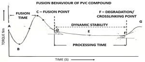
After fusion, torque drops to a relatively stable plateau where the material is fully molten and uniformly mixed. This plateau represents the steady-state melt viscosity of the formulation under shear conditions that resemble those in an extruder. Engineers use this value to predict motor load, screw speed limits, and temperature settings in subsequent processing. If the plateau is unstable or fluctuates, it often indicates incompatibility in the formulation or poor mixing characteristics. If mixing continues beyond this region, the torque eventually begins to decline, signaling polymer degradation due to thermal and mechanical stress. The time at which this decline begins defines the maximum safe residence time and the thermal stability window for processing. From one curve, the formulator extracts fusion time, peak torque, stable torque, and degradation onset, which together define how the material will behave during real processing. This level of insight cannot be obtained simply by observing the appearance of a mixed batch; it is a scientific measurement of processability.


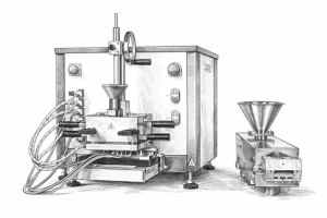
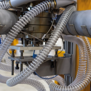
Figure 2 Internal Mixer

However, knowing that a formulation is processable rheologically does not guarantee that difficult fillers or pigments will disperse properly. That question is answered by the internal mixer, typified by equipment such as the Banbury mixer. This machine operates at a much larger scale, often from a few kilograms to tens of kilograms per batch, and is designed to apply extremely high shear and compressive forces. Inside its closed chamber, two heavy rotors rotate in opposite directions while a hydraulically operated ram forces the material downward. The mixing mechanism here is dominated by dispersive action. The material is repeatedly squeezed between the rotor tips and the chamber wall, stretched, folded, and recompressed. These actions generate intense localized stresses that physically break apart agglomerates of carbon black, silica, calcium carbonate, pigments, or other fillers. The high friction also causes rapid temperature rise, making thermal control more challenging than in the rheometer or extruder.

The internal mixer therefore serves as a practical stress test for the formulation. Operators monitor torque rise, temperature increase, and the visual condition of the batch when it is dumped. The goal is not precise measurement but confirmation that the formulation can withstand real mixing forces and achieve genuine dispersion. If agglomerates remain after internal mixing, they will certainly persist in a twin-screw extruder. Conversely, if proper dispersion is achieved here, it is a strong indication that the formulation is mechanically viable. The internal mixer thus bridges the gap between laboratory rheology and industrial reality by proving whether the material can survive and respond to aggressive mixing conditions.

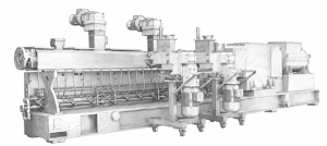
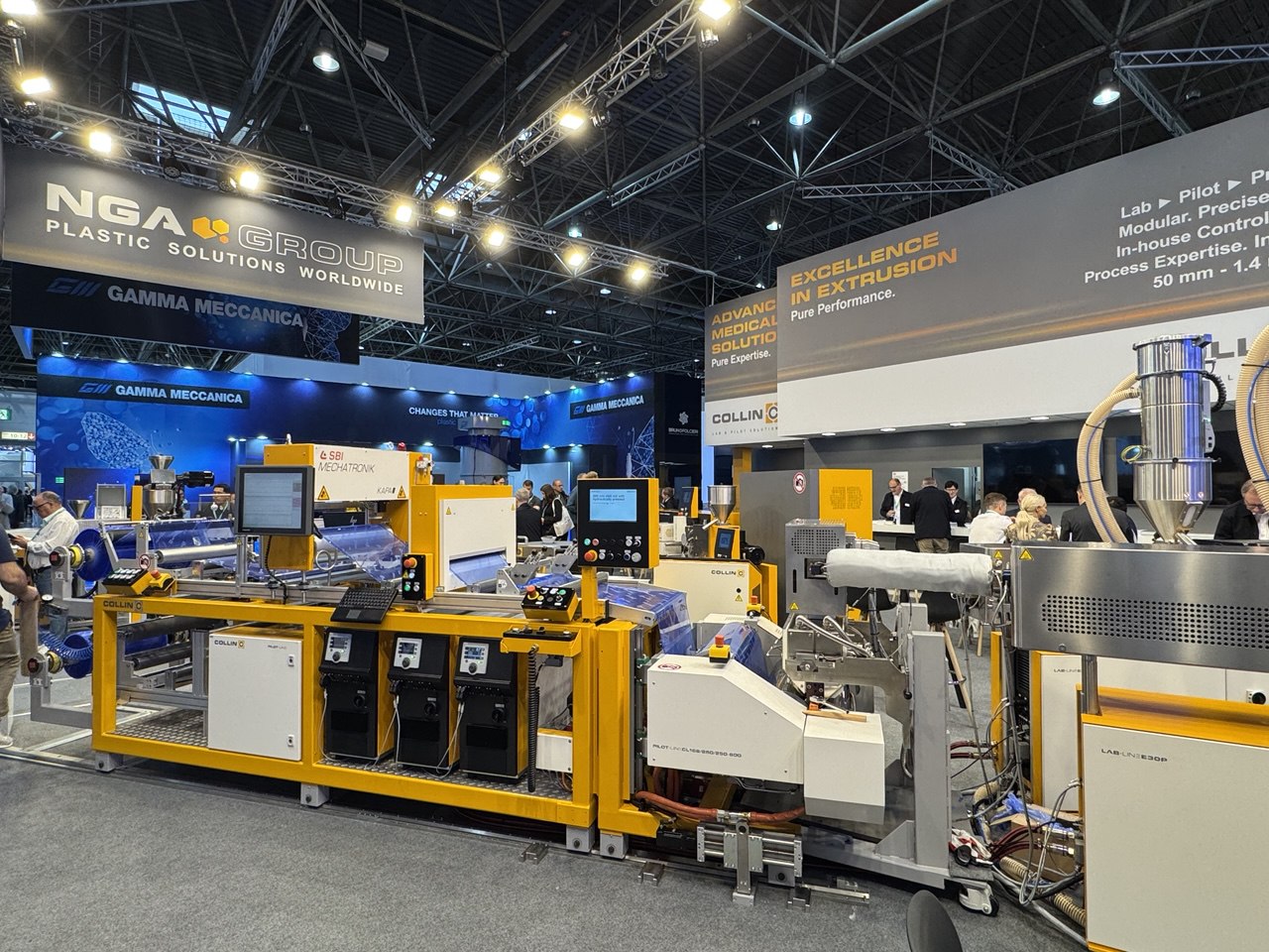
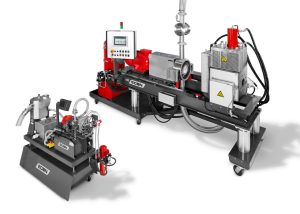
Figure 3 Twin Screw Compounder

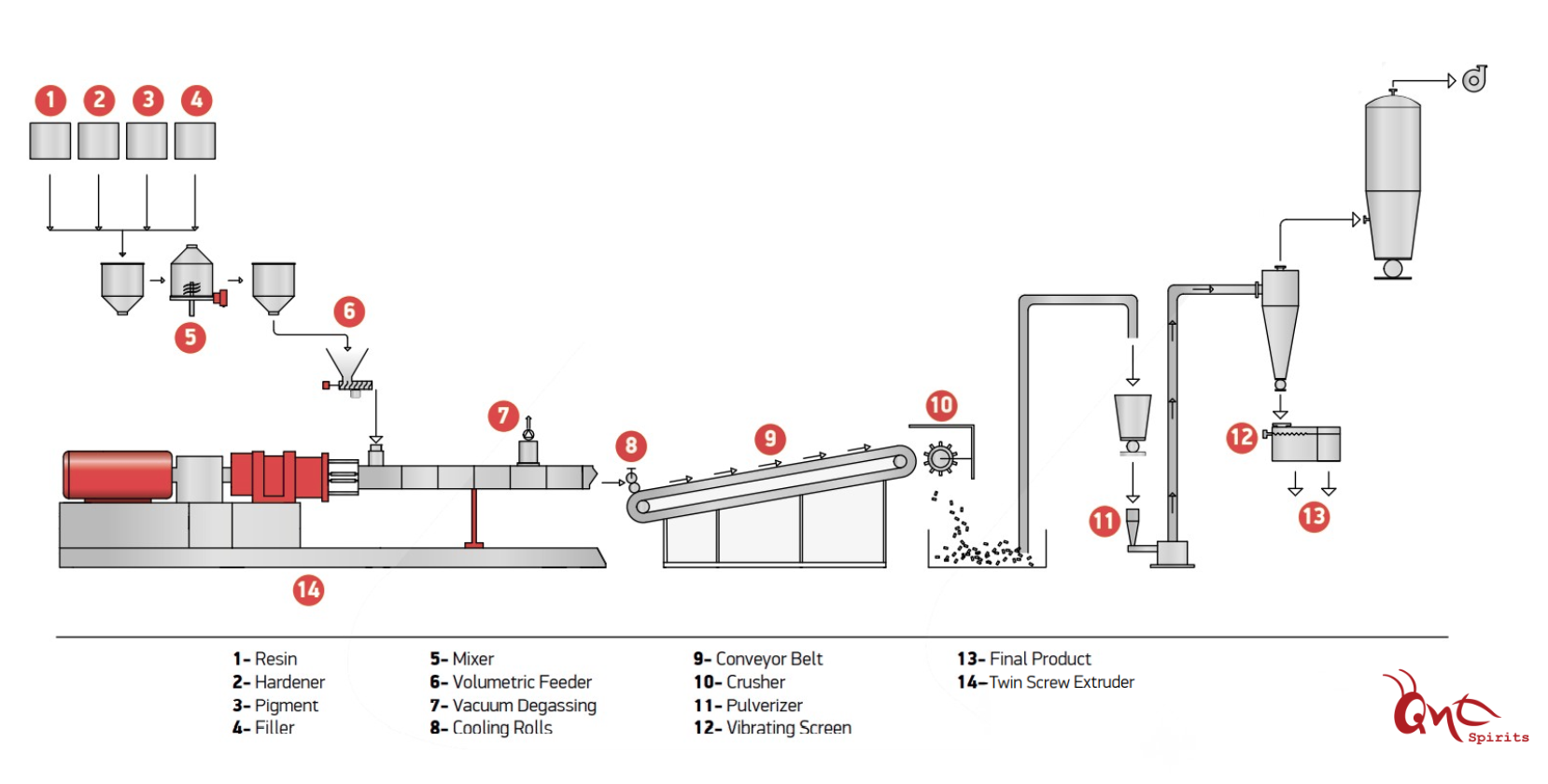
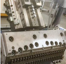
Once rheological behavior and dispersion capability are both understood, the formulation is ready to be translated into a continuous process using a twin-screw compounder. The twin-screw extruder is fundamentally different from the other two machines because it is designed as a modular, continuous processing platform rather than a batch mixer. Its screws are assembled from individual elements mounted on splined shafts, allowing engineers to design specific zones for conveying, melting, kneading, mixing, venting, and pressurizing. Forward-pitch conveying elements transport the material along the barrel. Kneading blocks, set at particular stagger angles, create controlled regions of high shear for dispersive mixing. Specialized mixing elements provide distributive mixing to ensure uniform distribution of additives without excessive shear. Barrel heaters and cooling channels maintain a carefully defined temperature profile across multiple zones. Side feeders introduce fillers or reinforcements at precise points where the polymer is sufficiently molten, and vacuum vents remove moisture or volatiles. The final sections build pressure to push the homogeneous melt through a die for pelletizing.

The configuration of these screw elements is guided directly by what was learned earlier. Fusion time from the torque rheometer influences where melting sections should be located and how long the material should remain there. The stable torque value helps determine appropriate screw speed and feed rate to avoid overloading the motor. Knowledge gained from the internal mixer about how stubborn fillers behave dictates the intensity and placement of kneading blocks to maintain dispersion without degrading the polymer. Even decisions about venting and additive feeding points are influenced by understanding when the material becomes fully molten and how it responds to shear.

Taken together, these three machines form an integrated knowledge and production chain. The torque rheometer provides the scientific fingerprint of the formulation’s behavior under shear and heat. The internal mixer proves that the formulation can achieve proper dispersion under severe mechanical forces. The twin-screw extruder uses this combined knowledge to design a stable, continuous, and repeatable compounding process capable of running for hours or days at industrial throughput. The progression from grams to kilograms to tons per hour is not merely an increase in scale but a transition from understanding, to proving, to manufacturing. Mastery of polymer compounding depends on recognizing how these machines complement one another and how the data and observations from each stage inform the next, minimizing trial-and-error and ensuring reliable scale-up from laboratory formulation to full production.

Contact Us

Ant Spirits Sdn Bhd (201201027599)
Ant Spirits PTE LTD (202332416D)
PT. Ant Spirits Indonesia (1000000007408146)
Send us a Message
Whatapps Us